

Vol. 39 (Number 24) Year 2018 • Page 33
A.M. DOSTIYAROV 1; D.R. UMYSHEV 2; G.S. KATRANOVA 3
Received: 09/05/2018 • Approved: 30/05/2018
2. Experimental set-up and method
ABSTRACT: The experimental studies of a two-stage burner in the combustion chamber of a transport gas turbine engine (GTE) were carried out, which confirmed the possibility of achieving high combustion efficiency, ηfuel, a low degree of temperature field unevenness and a significant decrease in NOx emission. The concentrations of NOx and CO were measured for various excess air factors in two tiers of the burner. The effect of various air supply modes, i.e. changes in the excess air factor in the tiers, on fuel efficiency was tested. A computational modeling of the flow in a two-stage burner was carried out. The contours of the recycle zones and the calculation of the non-mixture coefficient were presented. The findings corresponded to the obtained experimental data. For the best option of the "air" nozzle in the design condition, the following indicators were obtained: - combustion efficiency ηfuel = 0.98-0.995; - wall temperature Тw = 3200C; - degree of irregularity of the temperature field θ = 6.5%; - NOx concentrations CNOx <20 ppm. |
RESUMEN: Los estudios experimentales de un quemador de dos etapas en la cámara de combustión de un motor de turbina de gas de transporte (GTE) se llevaron a cabo, lo que confirmó la posibilidad de lograr una alta eficiencia de combustión, combustible, un bajo grado de desigualdad en el campo de temperatura y una disminución significativa en Emisión de NOx Las concentraciones de NOx y CO se midieron para diversos factores de exceso de aire en dos niveles del quemador. Se probó el efecto de varios modos de suministro de aire, es decir, cambios en el factor de exceso de aire en los niveles, en la eficiencia del combustible. Se llevó a cabo un modelado computacional del flujo en un quemador de dos etapas. Se presentaron los contornos de las zonas de reciclaje y el cálculo del coeficiente de no mezcla. Los hallazgos correspondieron a los datos experimentales obtenidos. Para la mejor opción de la boquilla "aire" en las condiciones de diseño, se obtuvieron los siguientes indicadores: - eficiencia de combustión η combustible = 0.98-0.995; - temperatura de la pared Тw = 3200C; - grado de irregularidad del campo de temperatura θ = 6.5%; - Concentraciones de NOx CNOx <20 ppm. |
Particular attention in the development of new combustion chambers of gas turbine units (GTUs) currently is paid to creating an optimal temperature field in the diluent zone, developing the efficient methods of fuel injection, which operated at different pressures and rates, decreasing the size of units and reducing the formation of hazardous substances.
As many researches and practice show (Lefebvre, 2010), a significant part of NOx formations is nitrogen, which is formed during the building-up process of local volumes (areas) of high temperatures and the long time stay period of gases in the combustion zone.
Previous works by the authors (Umyshev et al., 2016(a, b); 2017(a, b)) showed that the reduction of hazardous emissions and flame stabilization is possible by means of high-drag bodies in the form of angle stabilizers. However, the use of angle stabilizers has one minus – significant route pressure losses in the combustion chamber. Based on this, the authors conducted an analysis of the methods that ensure low pressure losses and NOx emissions. The main problem in the reduction of NOx is the heat.
To reduce the heat, the technology of lean-premixed combustion is widely used and studied. This technology is explored by many researchers. The authors of this article suggest a lean-premixed mixture that burns in discrete zones – microflame combustion.
The analysis of operation of the Alstom EnVironmental (EV) burners is carried out by Cho et al. (2013). These types of burners have been used relatively recently. Their distinctive feature is the mixing of the fuel-air mixture before it is fed into the combustion chamber. The burner consists of two cones, between which the gas is mixed with primary air. By this specific form, the burner provides good mixing, thereby increasing the mixture homogeneity, which reduces the formation of local volumes of high temperatures and improves combustion stability. The flame stability is maintained by the destruction of the whirl at the burner outlet. The authors also showed that the premixing of the fuel in the burner itself reduces the emission of hazardous substances, in particular NOx. This was noticed when using a different number of bores made in the burner.
Microflame combustion also includes burning behind high-drag bodies.
For example, Fan et al. (2014) studied the combustion processes behind angle stabilizers. The authors figured out that flame stabilization by high-drag bodies allows improving the stall characteristic. The article states that the stall occurs in areas with the speeds of 36 and 43 m/s and in the depletion region.
Another direction is the use of swirling motion of the fuel-air mixture to stabilize the flame and improve performance (Stöhr et al., 2009; 2012). The authors of these papers proposed a gas turbine model combustor in which air passes through two radial vortex generators at room temperature. Afterwards, these two swirling flows enter the combustion chamber through a central bore. The fuel is fed through the ring opening. The experimental studies showed good stabilization rates.
Belohradský et al. (2013) use a two-stage combustion chamber. In the combustion chamber, the gas is fed from two groups of nozzles. On the axis of the combustion chamber, swirled vanes – flame stabilizers – are installed. They consist of eight blades and are mounted on a central tube.
The experimental study by de Almeida and Lacava (2015) covers a two-stage burner for a gas turbine, in which such parameters as total air excess, Reynolds numbers and swirler angles were changed. The research showed that when these parameters contribute to recirculation zone intensification formed at secondary chamber, i.e. higher swirler angles and smaller Reynolds numbers, CO and UHC are reduced.
Fernando and Felic (2007), Kim et al. (2015), Gao et al. (2012) studied the effect of various options for creating recirculation zones that ensure low hazardous emissions. The results of an experimental study of the so-called vortex trap are given in the paper by Kim et al. (2015). The results showed that the vortex trap reduces NOx emissions by 21.2%, and CO – by 13.3%.
Gao et al. (2012) studied a two-stage burner separated by pellets. The influence of the size of pellets on hazardous emissions was determined. The authors found the optimal ratios of parameters ensuring low NOx emissions.
Jing et al. (2011a) carried out an analysis of a burner with two vortices and the effect of diluent air. The results showed that an increase in diluent air reduces the number of particles in the secondary air supply, but increases the number of particles in the near-wall zone. A study by Jing et al. (2011b) on the influence of the angle of the secondary blades on the particle flux showed that a decrease in the angle leads to a decrease in the root-mean-square value of the axial, radial velocities in the near-wall zone, but results in an increase in the tangent velocities, as well as a slight increase in the recirculation zone. A study by Tia et al. (2017) on the influence of the outer secondary air vane angle on the parameters of the combustion process and NOx emissions showed that at 20°-30° angles the emission of NOx is reduced by 25% (from 325 mg/m3 to 237 mg/m3). The cold (non-burning) studies of solid fuel burners by Li et al. (2012a) and Li et al. (2012b) showed that there is a central recirculation zone located at x/d=0.1-0.3 and r/d=0.25-0.4 at a velocity of 4 m/s saturated with oxygen that potentially produces NOx.
The further improvement of GTE combustion chambers required the development of a multifuel burner that would ensure the efficient combustion of fuels and the reduction of hazardous emissions (CO, HC, NOx) throughout the operational range of engine conditions. To this end, a new design of the microflame device was developed, a two-stage burner, which makes it possible to organize the combustion process in a number of discrete zones, i.e. microflame combustion. In this case, the transverse arrangement of zones takes place. In the concept of zone combustion, the focus is on optimizing the fuel distribution, and the purpose is to regulate combustion to achieve the low levels of toxic emissions under all operating conditions. A two-stage burner uses a fuel and air premixing and zone feeding of the combustible lean mixture into the combustion zone, i.e. the bulk of air is fed through the combustion chamber flame tube head.
The layout diagram of the experimental set-up is shown in Figure 1.
Figure 1
Layout diagram of the experimental set-up
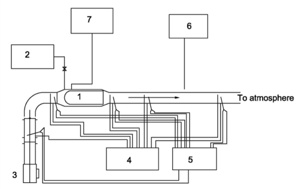
1 - combustion chamber; 2 - fuel supply; 3 - air compressor; 4 - group of U-shaped manometers;
5 - group of thermocouples; 6 - gas sampler for analysis; 7 - current supply for the spark plug.
The experimental set-up consists of an air compressor that supplies air under pressure to the combustion chamber. A line for supplying liquid fuel is connected to the combustion chamber. The combustion chamber is equipped with a spark plug connected to a current transformer operating from the main power supplies. In the sections shown in Figure 1, U-shaped manometers and thermocouples are installed. To study the concentrations of NOx and CO, a stationary gas analyzer is used.
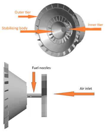
Figure 2 presents a 3D model of the studied two-stage burner, which consists of a liquid injector, an inlet vane swirler and a vane swirler around it, and a ring nozzle. On the output front, the burner is equipped with coaxial shells separating the front of the burner into tiers. Each tier has a group of vane swirlers. The inner circle is installed around the stabilizing cone. Input and output vane swirlers were manufactured at different angles – from 20º÷60º.
The material of the blades used in the MFP is a heatproof high alloy. Naturally, the choice of the material for the blades of microflame combustion should be determined by the conditions of their operation and, primarily, by the temperature regime.
Figure 2
3D model of the burner under study


The dependence of fuel combustion efficiency on the total excess air factor during the operation of the combustion chamber is shown in Figure 1.
Figure 3
Dependence of fuel combustion efficiency on total excess air
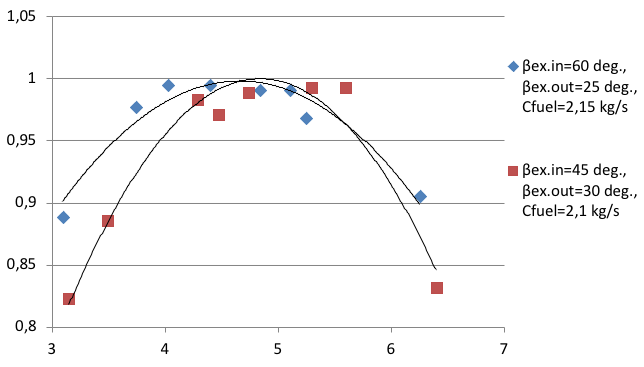
Figure 4
Dependence of fuel combustion efficiency on αex.in at αex.out=const
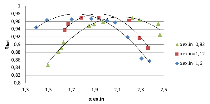

Figure 5
Dependence of fuel combustion efficiency on αex.in at αex.out=const.
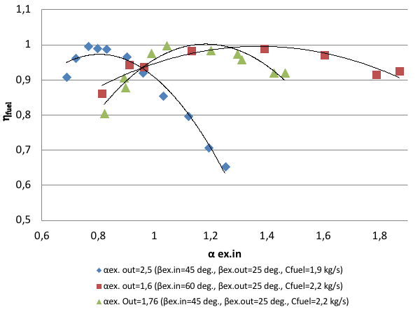

Figure 6
Dependence of fuel combustion efficiency on the parameter m at α∑=const.
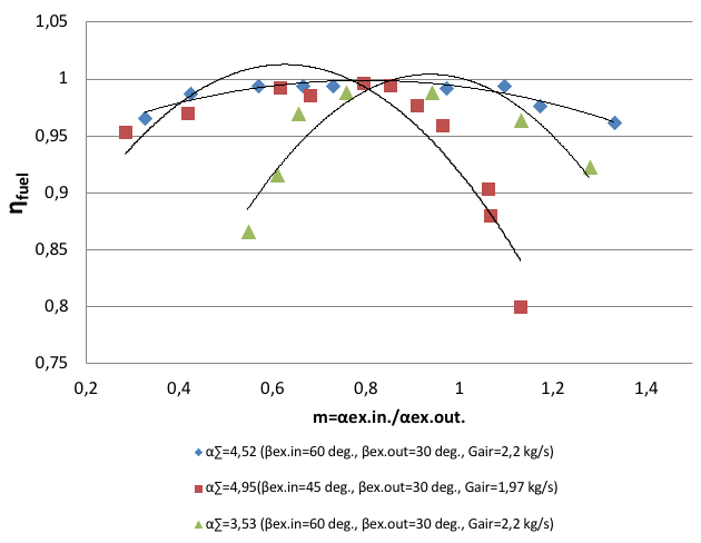
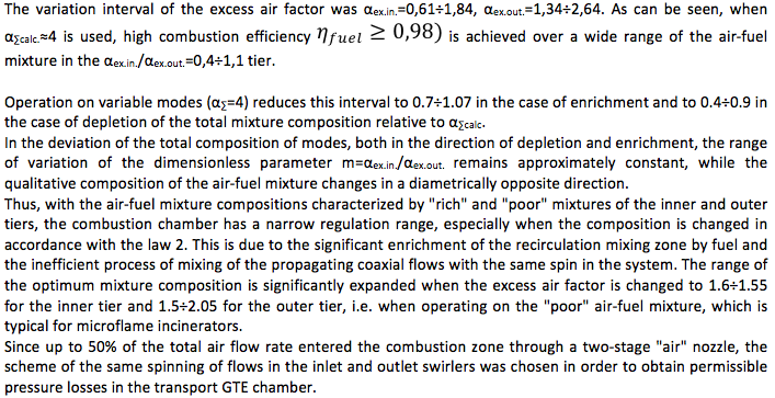

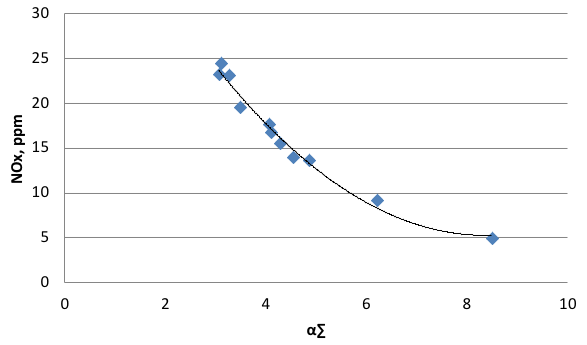
Figure 7
Dependence of NOx formation on α∑
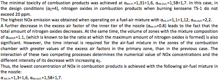
One of the tasks set in the development of a two-stage "air" nozzle was the creation of a burner device that makes it possible to obtain a controlled, regulated temperature field at the exit of the combustion chamber with a low degree of unevenness.
The temperature field at the exit of the combustion chamber is determined not only by the nature of the combustion process, heat exchange and mixing in the corresponding zones of the flame tube, but also by the specific design of the combustion chamber, its front device: the structure of the formed flame, the fuel atomization characteristic, the angle and range of the fuel flame.
A cardinal way to significantly improve the temperature field is the realization of the microflame fuel combustion method, which makes it possible to avoid the separation of air into primary and diluent, i.e. to supply all air through the front of the combustion chamber. In this case, the processes of dilution and mixing of combustion products and excess air flow inside the entire length of the flame tube and are determined by the length and diameter of the flame tube as well as by pressure drops on its walls. Therefore, to generalize the experimental data on the degree of unevenness of the transport field at the exit of the combustion chamber of the multilevel "air" nozzle, the following dependence was chosen:
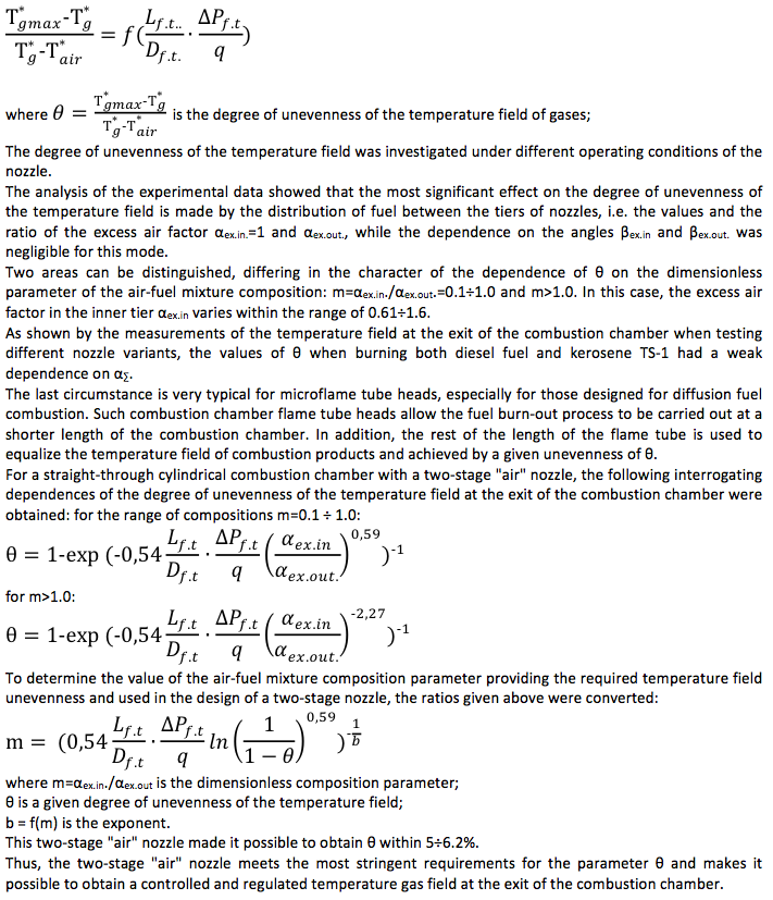
Figure 7
Flow recirculation contours
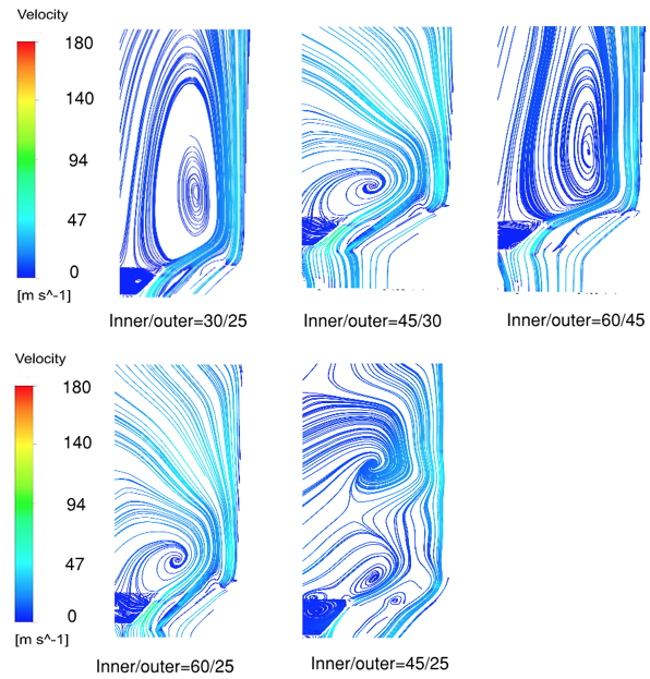

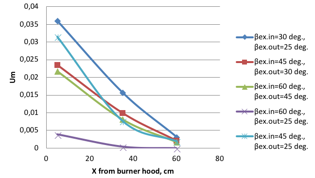
Figure 8
Indicator of modified unmixedness at the burner axis
Lefebvre A. H., Ballal, D. R. (2010). Gas turbine combustion: Alternative Fuels and Emissions, Third Edition. Taylor & Francis.
Umyshev, D. R., Dostiyarov, A. M., Tumanov, M. Y., Wang, Q. (2017(a)). Experimental investigation of v-gutter flameholders. Thermal Science, 21(2), 1011-1019.
Umyshev, D. R. et al. (2016(a). Application of semi perforated v-gutter flameholders in heat-generating systems for autonomous building heating. International journal of mechanics and mechanotronics, 16(6), 63-69.
Umyshev, D. R., Dostiyarov, A. M., Tumanov, M. Y., Tuytebayeva, G. M. (2016(b)). Experimental investigation of recirculation zones behind v-gutter type flameholders. International Journal of Pharmacy and Technology, 8(4), 27369-27380.
Umyshev, D. R., Dostiyarov, A. M., Tyutebayeva, G. M. (2017(b)). Experimental investigation of the management of NOx emissions and their dependence on different types of fuel supply. Espacios, 38(24), 17.
Cheon Hyeon Cho, Gwang Min Baek, Chae Hoon Sohn, Ju Hyeong Cho (2013). A numerical approach to reduction of NOx emission from swirl premix burner in a gas turbine combustor. Applied Thermal Engineering, 59, 454-463.
Aiwu Fan, Jianlong Wan, Yi Liu, Boming Pi, Hong Yao, Wei Liu (2014). Effect of bluff body shape on the blow-off limit of hydrogen/air flamein a planar micro-combustor. Appl. Therm. Eng., 62, 13-19.
Stöhr, M., Sadanandan, R., Meier, W. (2009). Experimental study of unsteady flame structures of an oscillating swirl flame in a gas turbine model combustor. Proceedings of the Combustion Institute, 32, 2925–2932.
Stöhr, M., Boxx, I., Carter, C.D., Meier, W. (2012). Experimental study of vortex-flame interaction in a gas turbine model combustor. Combustion and Flame, 159, 2636–2649
Belohradský, P., Skryja, P., Hudák, I. (2013). Experimental study on the influence of oxygen content in the combustion air on the combustion characteristics. Chemical Engineering Transactions, 35, 1147-1152.
De Almeida, D. S., Lacava, P. T. (2015). Analysis of Pollutant Emissions in Double-Stage Swirl Chamber for Gas Turbine Application. The 12th International Conference on Combustion & Energy Utilisation – 12ICCEU. Energy Procedia, 66, 117 – 120.
Fernando, B., Felic, G. (2007). Effect of pressure and fuel-air unmixedness on NOx emissions from industrial Gas turbine burners, Combust. Flame, 151, 274-288.
Gu Kim, Young Duk Lee, Chae Hoon Sohn, Keun Won Choi, Han Seok Kim (2015). Experimental investigation on combustion and emission characteristics of a premixed flame in a gas-turbine combustor with a vortex generator. Applied Thermal Engineering,77, 57-64.
Huai-Bin Gao , Zhi-Guo Qu , Ya-ling He , Wen-Quan Tao (2012). Experimental study of combustion in a double-layer burner packed with alumina pellets of different diameters. Applied Energy, 100, 295-302.
Jianping Jing et al. (2011a). Influence of the mass flow rate of secondary air on the gas/particle flow characteristics in the near-burner region of a double swirl flow burner. Chemical Engineering Science, 66(12), 2864-2871.
Jianping Jing et al. (2011b). Influence of the outer secondary air vane angle on the gas/particle flow characteristics near the double swirl flow burner region. Energy, 36(1), 258-267.
Shuguang Tia et al. (2017). Effect of outer secondary air vane angles on combustion characteristics and NOx emissions for centrally fuel rich swirl burner in a 600-MWe wall-fired pulverized-coal utility boiler. Applied Thermal Engineering, 125, 951-962.
Zhengqi Li. (2012a). Cold experimental investigations into gas/particle flow characteristics of a low-NOx axial swirl burner in a 600-MWe wall-fired pulverized-coal utility boiler. Experimental Thermal and Fluid Science, 37, 104-112.
Zhengqi Li et al. (2012b). Influence of staged-air flow on flow characteristics in a scale model of a down-fired utility boiler with swirl burners: An experimental study. Fuel, 93, 160-166.
1. Department of Heat power engineering, Seifullin Kazakh Agro Technical University, Kazakhstan, Doctor of Technical Sciences, Professor
2. Department of Power Engineering, Kazakh National Research Technical University after K.I. Satbayev, Kazakhstan, PhD
3. Department of Thermal power plants, Almaty University of Power Engineering and Telecommunications, Kazakhstan, Doctorate (doctoral student)